
A manifold and a pump group - how to combine them and when to use them? Find out in the article below.
In a nutshell:
- The pump group assembly is used in installations fed by a high temperature heat source, such as a gas boiler.
- The constant-value pump group mixes heated water with chilled water returning from the surface heating system.
- ZR and ZT valves are responsible for the degree of mixing.
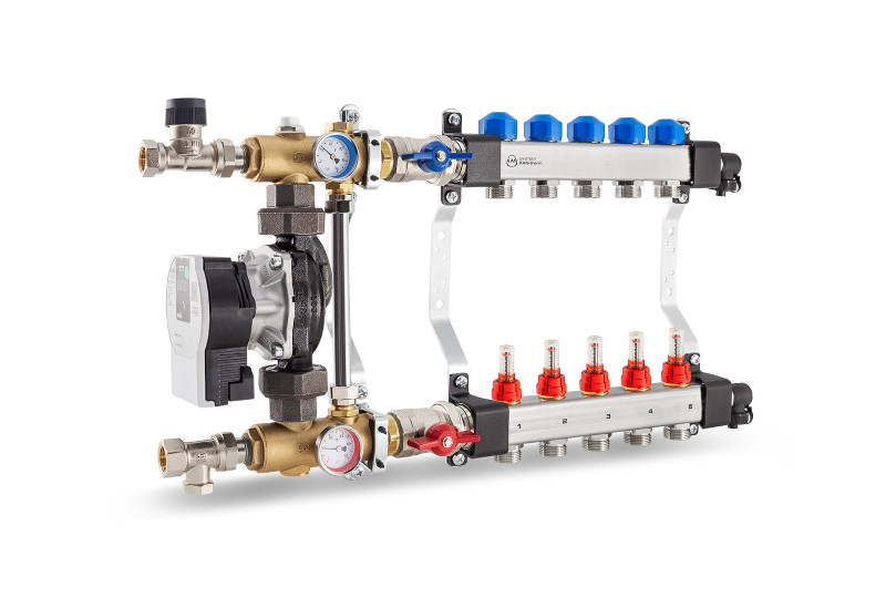
Constant-value pump group operation – explanation
The system operates on the principle of mixing heating water from the heating source with the water from loops return. The mixing pump directs some water, which has the temperature proper for surface heating, to the loops supplying manifold, and some, through the ZR control valve, to the system supplying installation return pipeline.
ZR and ZT valves - what they are used for?
The proper degree of water mixing is achieved by adjusting the ZR control valve. Before mixing, the water supplied to the system flows through ZT thermostatic valve, which can be controlled by a heading with contact sensor, placed on coils supplying manifold beam. The valve makes it possible to set a fixed temperature and protect against overheating (it makes it impossible to supply on surface heating higher temperature than adjusted).
Underfloor temperature monitoring - how does it work?
The adjustment of surface heater power is made through, located at the manifold’s beam, thermostatic valves, controlled by electric actuators, connected with room thermostats. Embedded in the by-pass set with a control valve, protects the pump in case of simultaneous closing of all valves on the supplying manifold and cutting off of all loops (e.g. at simultaneous closing of all actuators on manifold thermostatic valves).
The pump group and the heat source
Those systems shall not function properly with low-temperature heating sources, e.g. condensing boilers. The minimum required supply temperature of the system (in order to ensure an appropriate temperature of the water after mixing) is 60 °C. For this reason, we recommend using mixing systems based on three way thermostatic valves to operate with low-temperature heating sources. 86 Constant value pump groups as well as manifolds with an integrated mixing unit, series: USFP and USVP enable operation in surface heating systems up to 10 circuits (maximum heat load up to 15 kW).
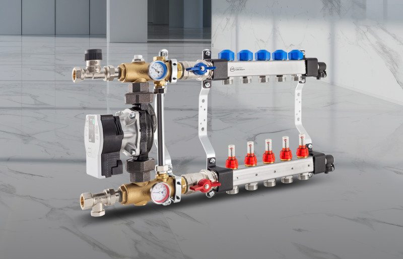
Operation of the pump group with a thermostatic three-way valve
The system is supplied with hot water from the installation through a three-way thermostatic valve, and from the return of the underfloor heating loops (return beam), thanks to which the mixing and lowering of the temperature of water supplied to the manifold supply beam (supplying the underfloor heating coils) takes place. Water circulation is obtained by the pump. The water returns to the system through the right outlet.
With a thermostatic three-way valve, how should the underfloor heating temperature be set?
The appropriate temperature of the medium after mixing is obtained by changing the setting on the three way thermostatic valve. If electric servomotors are installed on all loops circuits, the automatic control unit should be equipped with a module that turns off the pump when all circuits are closed. Alternatively, one manifold circuit can be left without automatic control. This will protect the pump against pumping water into a closed system.
The pump group with a thermostatic three-way valve - correct connection
Pay attention to the correct integration of the system into the rest of the installation. The mixing valve should be connected to the supply pipeline. In the case of extended installations, it may be necessary to apply an additional throttle valve at the inlet to the pump group.
Adjustment of the thermostatic mixing valve – a table
In order to set the desired temperature after mixing, remove the plastic protective cap of the three-way valve (snap fastening) and select the appropriate valve setting:
|
Setting |
Water temperature after mixing ATM 363 |
Water temperature after mixing ATM 361 and ATM 561 |
|
1 |
35 °C |
20 °C |
|
2 |
44 °C |
25 °C |
|
3 |
48 °C |
30 °C |
|
4 |
51 °C |
34 °C |
|
5 |
57 °C |
38 °C |
|
6 |
60 °C |
43 °C |
*Temperature values are given with an accuracy of ±2 °C
Pump groups of this type are delivered with three-way thermostatic valves with two different Kv values (1,6 and 2,5):
- Pump groups with a three-way thermostatic valve with Kv = 1,6 should be used for smaller systems (up to 6 heating circuits with a thermal power load up to 7,5 kW).
- Pump groups with a three-way thermostatic valve with Kv = 2,5 can be used with larger systems (up to 12 heating circuits with a thermal power load of up to 15 kW).